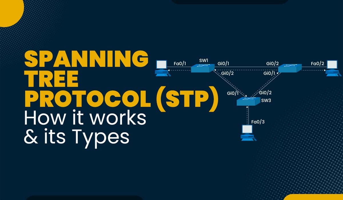
One of the critical protocols designed to maintain network stability and prevent looping issues is the Spanning Tree Protocol (STP). Understanding STP is essential for network administrators and IT professionals as it plays a crucial role in the design and operation of local area networks (LANs). This article delves into the basics of the Spanning Tree Protocol, its importance, how it works, and its various iterations.
What is Spanning Tree Protocol?
The Spanning Tree Protocol (STP) is a network protocol that ensures a loop-free topology for any bridged Ethernet local area network. STP was introduced as a solution to prevent network loops, which can cause significant issues like broadcast storms and MAC table instability. The protocol operates at the data link layer (Layer 2) of the OSI model, and its primary function is to detect and eliminate loops by creating a spanning tree that logically blocks redundant paths in the network.
The Importance of STP
Network loops occur when there are multiple active paths between two network nodes. These loops can lead to several problems:
- Broadcast Storms: Continuous broadcast traffic can consume a significant portion of network bandwidth.
- MAC Table Instability: Switches struggle to accurately map MAC addresses to ports, leading to network disruptions.
- Duplicate Frames: Multiple copies of the same frame can be delivered to the destination, causing confusion and additional load.
STP addresses these issues by ensuring that only one active path exists between any two network devices. By doing so, it maintains network efficiency and stability.
How STP Works
STP works by designating a single switch as the root bridge and then calculating the shortest path from the root bridge to all other switches in the network. The process involves several key steps:
1. Root Bridge Election
The first step in STP operation is electing the root bridge. All switches in the network participate in this election, and the switch with the lowest Bridge ID (BID) becomes the root bridge. The BID is a combination of the switch’s priority value and its MAC address. The switch with the lowest BID is preferred.
2. Path Cost Calculation
Once the root bridge is elected, STP calculates the path cost to determine the shortest path to the root bridge. Each network segment is assigned a cost based on its bandwidth. For instance, a 10 Mbps link has a higher cost than a 100 Mbps link. STP adds up these costs to find the most efficient path from each switch to the root bridge.
3. Port Roles Assignment
STP assigns roles to each port on a switch to manage the paths and prevent loops:
- Root Port (RP): The port on a switch with the lowest path cost to the root bridge.
- Designated Port (DP): The port on each network segment with the lowest path cost to the root bridge. This port forwards traffic for the segment.
- Blocked Port: Ports that do not participate in forwarding to prevent loops. These ports remain in a blocking state.
4. Transition States
STP ports transition through several states before starting to forward frames:
- Blocking: Ports do not participate in frame forwarding or learn MAC addresses.
- Listening: Ports listen for BPDU (Bridge Protocol Data Unit) frames to ensure there are no loops.
- Learning: Ports start learning MAC addresses but still do not forward frames.
- Forwarding: Ports forward frames and continue to learn MAC addresses.
- Disabled: Ports are administratively down.
Iterations of STP
Over time, several enhancements to the original STP have been developed to improve network performance and convergence times. The main iterations include:
1. Rapid Spanning Tree Protocol (RSTP)
RSTP (IEEE 802.1w) is an evolution of STP designed to achieve faster convergence. Unlike STP, which can take 30-50 seconds to respond to changes, RSTP can typically respond within a few seconds. It introduces new port roles and states, allowing for more efficient transitions and improved network stability.
2. Multiple Spanning Tree Protocol (MSTP)
MSTP (IEEE 802.1s) allows multiple VLANs to be mapped to a single spanning tree instance, reducing the number of required STP instances and enhancing network scalability. MSTP combines the benefits of RSTP with VLAN support, providing more efficient network management.
3. Per-VLAN Spanning Tree Protocol (PVST and PVST+)
PVST and PVST+ are proprietary Cisco protocols that allow a separate spanning tree instance for each VLAN, optimizing traffic flow and redundancy. PVST+ extends PVST to support IEEE 802.1Q VLAN tagging.
Configuring STP
Configuring STP involves several steps, typically carried out on network switches. Here’s a basic example of how to configure STP on a Cisco switch:
plaintext
Switch# configure terminal
Switch(config)# spanning-tree mode {pvst | rapid-pvst | mst}
Switch(config)# spanning-tree vlan [vlan-id] root primary
Switch(config)# spanning-tree vlan [vlan-id] priority [value]
Switch(config)# spanning-tree portfast
Switch(config)# end
This configuration sets the spanning tree mode, assigns a root switch, sets priority values, and enables PortFast for immediate transition to the forwarding state on edge ports.
Conclusion
The Spanning Tree Protocol is a fundamental component in the toolkit of network administrators, ensuring the stability and efficiency of Ethernet networks. By preventing loops and managing redundant paths, STP keeps the network running smoothly, mitigating issues like broadcast storms and MAC table instability. Understanding STP and its iterations, such as RSTP and MSTP, is crucial for anyone involved in network design and management. As networks continue to evolve, STP remains a vital protocol, adapting to meet the demands of increasingly complex and dynamic environments.
